Seven assemblies on file — designed, simulated, and in most cases built and tested.
Longhorn Rocketry Association · Vehicle design
Rocket Version 9 — Active-Control Airframe
Airframe
3 in diameter · ≈ 32 in long
Control
4 servo-actuated canards
Tools
Fusion 360
Date
2026
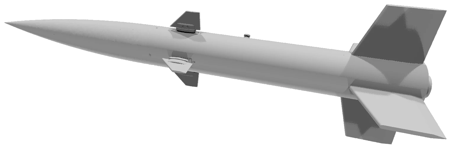
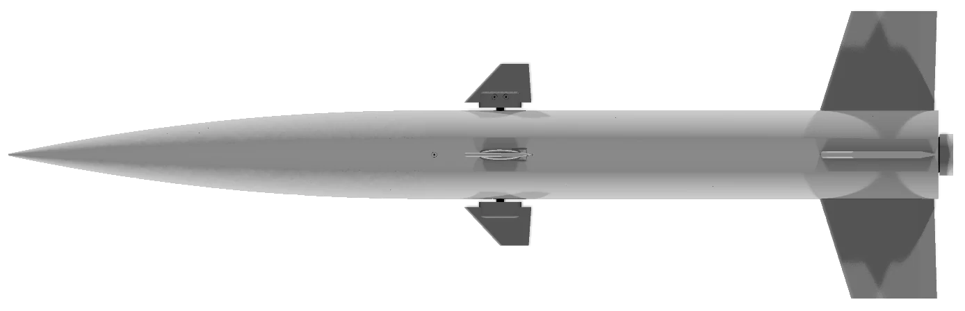
Modeled the full vehicle assembly in Fusion 360 — ogive nose cone, body tube, motor tube with centering rings and motor retainer, bulkhead, thread-insert ring, rail buttons, and four tail fins.
Integrated four forward canards on servo-driven mounts, with the servos, servo casings, horns and canard plates modeled in place for active flight control.
Sized the airframe at 3 in diameter — the envelope the TVC flight computer below was compacted to fit on its avionics sled.
3 inBody diameter
≈ 32 inOverall length
4Active canards
Rocket Version 9 — full Fusion 360 assembly, rendered from the STEP export.Side profile — forward canards and aft tail fins on the 3 in body tube.
Longhorn Rocketry Association · Avionics
TVC Flight Computer — LRA TVC V5
Board
50 × 76 mm · 4-layer
Processor
ESP32-WROOM-32E
Sensors
BMI088 IMU · BMP388 barometer
Tools
KiCad 10
Ported the team's flight-computer design from EasyEDA into a hierarchical KiCad project (Power, USB/Reset, Processor, Sensors and Pyro sheets), cross-checking every net against the original schematic and board files.
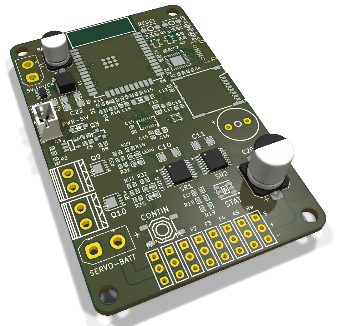
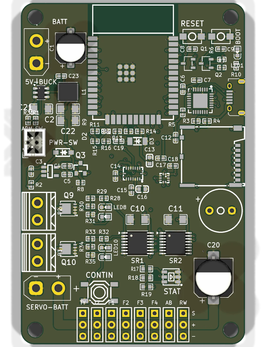
Reworked the outputs for active control: eight actuator headers — TVC pitch and yaw, four fins, airbrake and reaction wheel — fed from a dedicated servo battery bus kept separate from logic power, plus two pyro channels with continuity check.
Compacted the board from 65 × 80 mm to 50 × 76 mm on four layers with a solid ground plane so it mounts lengthwise in a 3 in airframe; the IMU sits at the board centre and the ESP32 antenna at the edge over a copper keep-out.
Replaced the power stage with a 2 A synchronous buck (AP63205), moved the shift registers to 74HCT595 to fix a 3.3 V-to-5 V logic-level problem on the pyro gates, and added an external arming switch.
Fully routed with zero unconnected nets and zero copper-clearance errors in KiCad DRC; design complete, ahead of fabrication.
50 × 76 mmBoard size
4Copper layers
8 + 2Actuator + pyro channels
KiCad 3D render — the eight actuator headers run along the bottom edge next to the servo battery input.Top view — switching supply top-left, ESP32 and USB-UART top-right, pyro drivers left, shift registers and servo power along the bottom.
IREC Competition Rocket · Longhorn Rocketry Association
Active Airbrakes Subsystem
System
Airbrakes
Team
LRA
Target apogee
10,000 ft
Date
2025 – Now
Designed an active airbrake system to shed roughly 2,500 ft of apogee and hold a 10,000 ft target altitude.
Selected a cam-slot actuation mechanism through trade studies favoring simplicity, low mass, and flight heritage.
Ran ANSYS Fluent CFD and Static Structural FEA to size aerodynamic loads and structural margins.
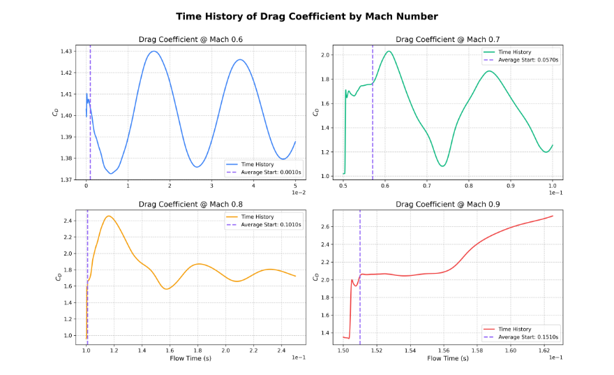
Ran transient CFD to capture oscillating vortex shedding on the airbrake bluff plate near Mach 1, extracting drag coefficient and drag force time histories across Mach 0.6–0.9 to validate the design.
Supported prototyping and test planning, refining tolerances, materials, and system integration.
SF > 2Structural margin
2,500 ftApogee reduction
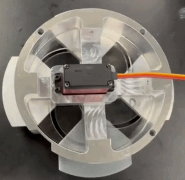
Transient CFD — drag coefficient time history across Mach 0.6–0.9, capturing vortex-shedding oscillation on the airbrake bluff plate.Prototype of the four-petal airbrake mechanism, servo-actuated from the center hub.
IREC Competition Rocket — target apogee 2,000 ft, max velocity 110 m/s
Actuating Fin Tabs — Roll Control
System
Fin Tabs
Team
LRA
Actuator
MKS HV6160
Date
2025 – Now
Given three months to design an actuating fin system compact enough for a 3" body diameter, robust enough for high-speed aerodynamic loads, and light enough to protect the altitude target.
Ran a trade study weighing a linkage-based mechanism against a tab-based design; selected the tab design for fewer failure points, lower mass, easier control integration, and better scalability.
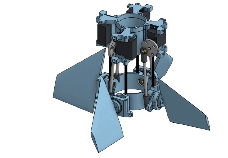
Built and maintained the CAD model in OnShape — a 14 mm-thick fin tab with an embedded slim servo, epoxied servo horn, and a dowel rod supporting rotation on the opposite side.
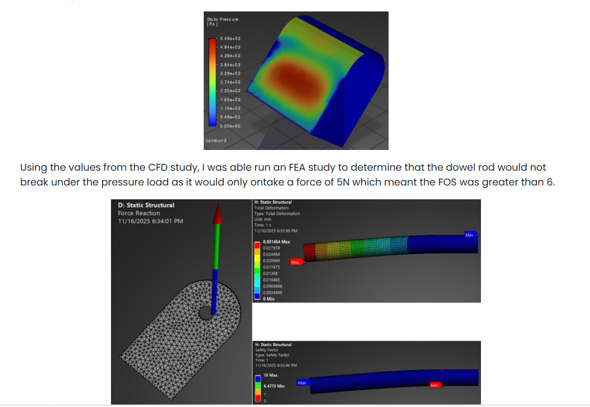
Used ANSYS CFD to find worst-case loading (tab actuated to 45°, 10x normal deflection) — 5,500 Pa static pressure, 2.6 N drag force, 1.25 drag coefficient.
Fed those loads into an FEA study confirming the dowel rod would see only 5 N under load, for a factor of safety greater than 6.
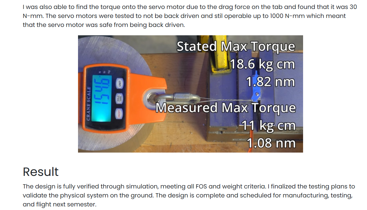
Calculated 30 N·mm of servo torque from drag loading against a rated 1,000 N·mm back-drive threshold, then bench-tested the servo (measured 1.08 N·m vs. 1.82 N·m stated max) to confirm it would not back-drive in flight.
FOS > 6Dowel rod margin
2.6 NDrag force
5,500 PaStatic pressure
OnShape assembly — three-fin actuating tab system with embedded servo motors and dowel-supported rotation.ANSYS CFD static pressure on the tab (top) feeding an FEA structural study of the dowel rod — deformation and safety factor (bottom).Bench validation — measured servo torque (1.08 N·m) against the stated max (1.82 N·m), confirming margin against back-driving.
Longhorn Rocketry Association — Advanced Research
Experimental Thrust Vector Control
System
Thrust Vector Control
Team
LRA Advanced Research
Tools
SolidWorks / OpenRocket / ANSYS
Date
2024 – Now
Works on the mechanical subteam to control an aerodynamically unstable rocket by directing engine thrust.
Designed and modeled a 2-axis gimbal TVC assembly in SolidWorks, simulated in OpenRocket for active thrust steering and in-flight attitude correction.
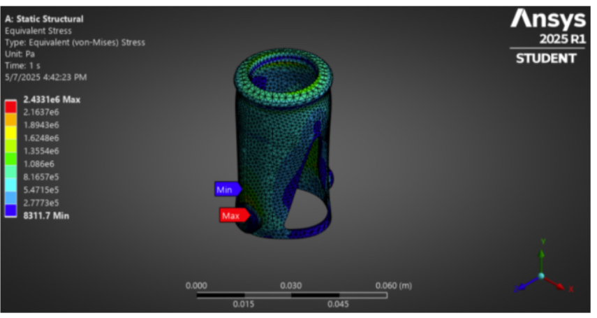
Ran ANSYS Static Structural FEA (equivalent von Mises stress) on the gimbal ring, iterating the design to stay within material stress limits.
Designed safety features so the rocket cannot aim toward the ground in the event of a mechanical failure.
ANSYS FEA — equivalent von Mises stress on the gimbal ring under load, peaking around 2.43 MPa near the mount points.
Propulsion Testing · LRA
Rocket Motor Test Stand
System
Motor Test Stand
Team
LRA
Tools
SolidWorks / KiCad
Thrust class
H (~150 lbf)
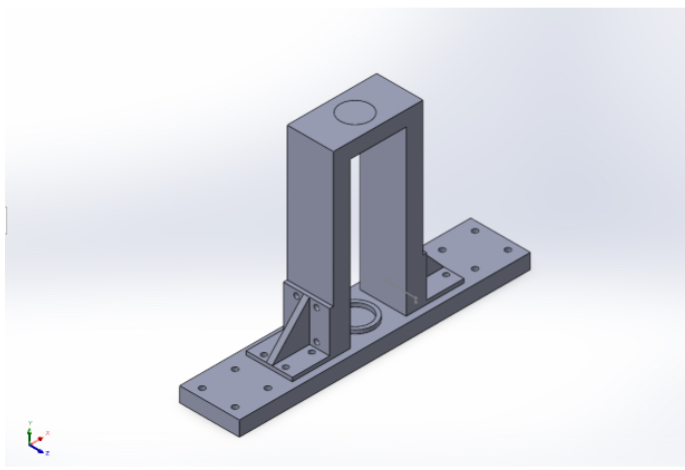
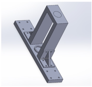
Designed and assembled a steel static-fire test stand for solid rocket motors, engineered to withstand H-class thrust levels (~150 lbf).
Designed the ignition and control electronics in KiCad for safe, remote motor ignition.
~150 lbfRated thrust
SolidWorks model of the static-fire test stand — steel frame sized for H-class motor thrust.Isometric view showing the motor mount and base-plate bracing.
UT Austin ECE Research, under Prof. Michael Becker
Additive Manufacturing — Atomic Strain Analysis
System
Strain Analysis
Team
M. Hernandez, S. Pinapati
Tools
OVITO / MATLAB / LAMMPS
Date
2024 – Present
Wrote code to parse and analyze large molecular-dynamics configuration files (.cfg) from LAMMPS simulations.
Generated strain density functions to characterize deformation in Al₂O₃ particles at the atomic scale.
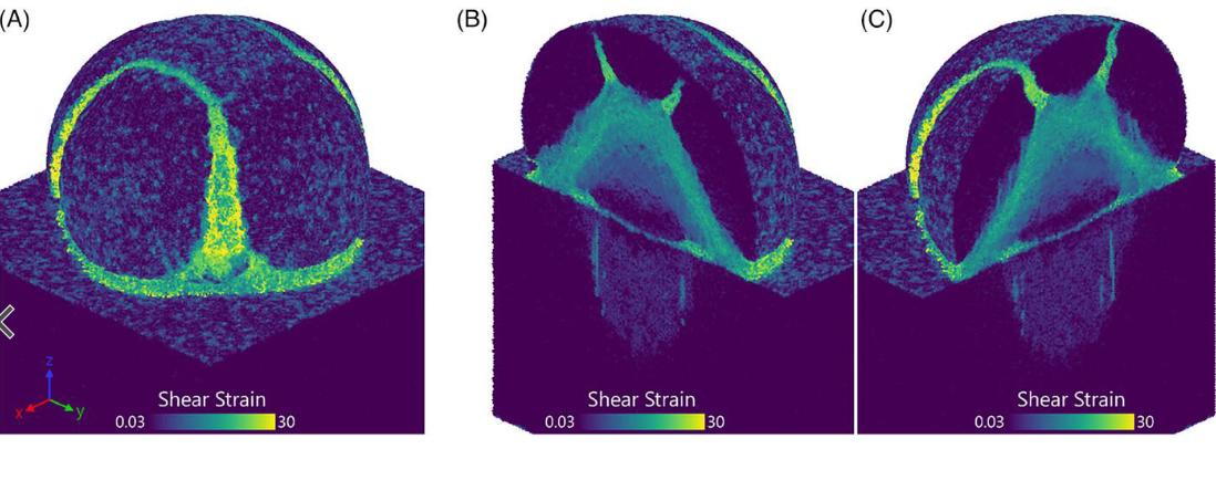
Examined how impact velocity and crystal orientation change resulting shear-strain distributions.
Visualized simulation output in OVITO and processed results in MATLAB to identify strain concentration patterns.
Shear strain density across three simulated impact cases — the banded high-strain regions (yellow) trace deformation paths through the particle.